Easting and Northing: British National Grid, ITM and US State Plane in CAD

Quick answer
Easting comes first, northing second — the same order as X and Y in CAD. The grid matters more than the digits: British National Grid tops out at 700,000 mE; Irish Grid stays under 500,000 on both axes; Irish Transverse Mercator runs 400,000–740,000 mE; State Plane and UTM eastings sit near 100,000–900,000 m. Confirm the grid, then the zone, then the datum — OSGB36 needs OSTN15 to reach WGS84, and NAD83 is not WGS84.
A coordinate file from the surveyor lands in the inbox, and the first row reads 530080.00, 180340.00 — or maybe 3114226.21, 10070436.13, or already converted to 51.5070, -0.1271. Before that point goes near a drawing, three questions decide whether the new main lands on the right side of the road or two streets over: which grid are these numbers from — British National Grid, Irish Grid, ITM, State Plane or plain UTM? Which zone, or which state? And which column is easting, which is northing? Get one wrong and the error runs from a couple of metres to a few hundred kilometres, and CAD draws the wrong answer exactly as confidently as the right one.
Easting first, northing second — always
Easting is the distance east of a grid's origin; northing is the distance north of it. Survey and CAD convention lists easting before northing, the same order as X then Y — the opposite of "latitude, longitude", where the north-south value comes first. That reversal, more than any datum error, is why a coordinate that looks fine on paper plots in the wrong hemisphere.
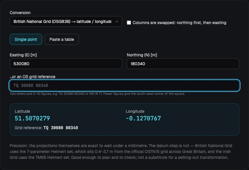
Take the pair 530000, 180000. On the British National Grid that is Horse Guards Parade in central London: 51.5040°N, 0.1284°W. As an Ordnance Survey grid reference the same point is TQ 30000 80000 — a two-letter code for the 100 km square, then five digits of easting and five of northing (fewer digits means less precision: eight figures is 10 m resolution, six is 100 m). Nudge it to TQ 30080 80340 — the exact reference the site's own converter uses as its worked example — and the point moves about 350 m north-east, to 51.5070°N, 0.1271°W, a stone's throw from Trafalgar Square.
A plausibility check worth memorising for British National Grid: northing runs from 0 near the Isles of Scilly to about 1,300,000 at Shetland, while easting never exceeds 700,000. A first number above 700,000 in a GB dataset means the columns are swapped, not that the point is offshore.
OSGB36 vs WGS84: what OSTN15 actually buys you
British National Grid coordinates are traditionally given on OSGB36, a datum fixed to the Airy 1830 ellipsoid through Great Britain's historic triangulation network. GPS, a web map or a modern survey works in WGS84 (or its European near-equivalent, ETRS89), on the GRS80 ellipsoid. The two disagree by around 100 m at the same point, so a raw OSGB36 pair plotted as if it were WGS84 lands visibly in the wrong field.
Ordnance Survey's official bridge is OSTN15, a grid-shift file described in their reference guide, A Guide to Coordinate Systems in Great Britain. It interpolates a locally varying shift across the country and, by OS's own figures, agrees with the underlying geodetic network to roughly a decimetre — survey-grade. The catch for a browser is size: OSTN15 is around 25 MB, awkward to ship to a web page. The practical fallback — used by proj4-based tools including this site's own — is the standard seven-parameter Helmert transform (EPSG:1314), one formula instead of a lookup grid. Checked against OSTN15 at seven points across Great Britain, that fallback comes out 0.40 to 3.69 m away, typically about 2 m. Fine for planning, siting an asset, or sanity-checking a survey; not fine for setting out or anything that has to close against a control network.
Ordnance Survey's own worked example, in Annexe C of the guide, is the Caister water tower near Great Yarmouth, Norfolk: OSGB36 latitude 52°39′27.2531″N, longitude 1°43′04.5177″E projects to British National Grid E 651409.903, N 313177.270 — exact to a fraction of a millimetre, because no datum change is involved yet. Push that easting and northing through the Helmert step to WGS84 and the answer is 52.6580°N, 1.7161°E, a few metres from the true OSTN15 result. That gap is the whole lesson: the projection is exact arithmetic; the datum step is what costs real metres.
Irish Grid vs ITM: same island, very different-looking numbers
Ireland runs two live grids, and the fastest way to tell them apart is the size of the numbers, not the label on the file. The Irish Grid (TM65, EPSG:29902) is the legacy system on the modified Airy ellipsoid: a single 500 km square, so both easting and northing stay under 500,000. Irish Transverse Mercator (ITM, EPSG:2157) was introduced in 2001 by Ordnance Survey Ireland — now part of Tailte Éireann — jointly with Ordnance Survey Northern Ireland, specifically to sit natively on ETRS89/GRS80 so GPS coordinates need no further translation. ITM's false origin is 600,000 mE, 750,000 mN, so its numbers run roughly 400,000–740,000 east and 520,000–970,000 north.
Take a point in central Dublin near O'Connell Bridge, 53.3498°N, 6.2603°W. In ITM that is E 715,826.51, N 734,697.59. In the Irish Grid the same point is E 315,900.56, N 234,671.36 — roughly 400,000 m apart in the raw numbers for the identical spot, which is exactly why magnitude alone settles it: an easting under 500,000 on Irish data is TM65/Irish Grid, over 500,000 it has to be ITM. The Irish Grid also carries its own Helmert datum step (EPSG:1642), with the same order-of-metres caveat as OSGB36; ITM, already on ETRS89, needs no such step beyond the roughly one-metre plate drift between ETRS89 and current WGS84.
US State Plane: 124 zones, two feet, and a datum that is not WGS84
The State Plane Coordinate System (SPCS83) is not one grid but 124 zones covering the 50 states, defined by the National Geodetic Survey on the NAD83 datum. Each zone is its own small Transverse Mercator or Lambert Conformal projection, sized so scale distortion stays under roughly 1 part in 10,000 — tight enough that site-level engineering can mostly ignore projection scale. That is why so many zones exist at all: covering the same ground with UTM's 6° zones allows distortion up to about 1 part in 2,500, loose enough for a map but not for control-quality survey work. A State Plane number means nothing without its zone name — "Texas Central", "California zone 3" — because neighbouring zones routinely reuse similar magnitudes with entirely different false origins.
NAD83 and WGS84 are close but not identical. They agreed to within about a metre when NAD83 was fixed in 1986, but the North American plate has drifted since, so current WGS84 realisations now sit roughly 1–2 m from NAD83 in the lower 48, and further apart in Alaska and Hawaii. Anything that has to tie into control monuments rather than just look right on a map needs NGS's own tools (NCAT, HTDP) and a stated epoch — a plain reprojection silently drops that gap.
Then there is the foot. The US survey foot is exactly 1200/3937 m; the international foot is exactly 0.3048 m — a difference of 2 parts per million, invisible on a short tape measurement and very much not invisible on a State Plane coordinate. A point in downtown Austin, Texas, in the Texas Central zone (EPSG:32139), has an easting of 3,114,226.21 US survey feet or 3,114,232.44 international feet — 6.23 ft, about 1.9 m, apart purely from which foot is applied, enough to put a manhole on the wrong side of a trench. NIST and NGS jointly retired the US survey foot at the end of 2022, but state legislation predating that decision, and plenty of CAD templates still in daily use, default to the old unit. State which foot a drawing is in; never assume.
UTM: the one grid that works anywhere
When a drawing gives a zone number and a hemisphere but no grid or state name, it is almost certainly UTM — the one system here that is not regional. UTM splits the globe into 60 zones of 6° each, with distortion up to about 1 part in 2,500 at a zone's edges: looser than State Plane, tight enough for most civil and utility work, usable anywhere without a lookup table. The Horse Guards Parade point from earlier sits in UTM zone 30N at E 699,294.41, N 5,709,783.43 — numbers with nothing in common with British National Grid's 530,000/180,000 for the identical spot, one more reminder that the grid identity decides more than the digits ever will.
Why did my drawing land somewhere else?
| Symptom | Likely cause | Fix |
|---|---|---|
| Off by a few metres to a couple of kilometres, right country | Datum mismatch — OSGB36 plotted as WGS84, or vice versa | Confirm the EPSG code or datum name; apply OSTN15 (or the Helmert fallback), not the raw numbers |
| Off by tens to hundreds of kilometres | Wrong UTM zone or wrong State Plane zone/state | Check the zone number or state name in the title block, the DXF header's EPSG code, or the survey report |
| Geometry mirrored or rotated against a base map | Easting and northing columns swapped | Check magnitude: BNG northing can exceed 700,000 but easting cannot; State Plane and UTM northing is routinely seven figures against a six-figure easting |
| Offset by a suspiciously round number (500,000, 600,000, 200,000…) | A false easting or false origin applied twice, or the wrong 100 km square | Re-derive the point from its geographic coordinates rather than patching the offset by hand |
| Small, growing gap across a large site, feet-based drawing | US survey foot mixed with international foot | Check which foot EPSG publishes for that zone and convert explicitly — do not assume a post-2022 file uses the new one |
| Fine locally, will not close against control monuments | NAD83 vs WGS84 (or ETRS89 vs WGS84) drift ignored | Use NGS's NCAT/HTDP, or the national equivalent, with a stated epoch — not a plain reprojection |
Big coordinates in CAD, and from a pasted table to a long section
None of these grids reaches the extremes of a seven-figure national system, but several still land far enough from a drawing's local origin to matter: a UTM northing can run past 5,000,000 m, a Michigan State Plane easting is deliberately offset by 4 to 8 million metres to keep every value in the state positive, and a State Plane easting in feet routinely runs past 3 million. CAD geometry runs on double-precision floating point, so working millions of units from the drawing origin quietly eats into the precision budget — lines that jitter on zoom, snaps that miss by a few millimetres, hatches that fail to close. The fix is the one used for any national grid: subtract a documented offset to bring the drawing near zero, and record that offset so the file can be pushed back to real-world coordinates later.
That offset only matters up to the point coordinates enter the drawing. Once the route exists, the long section itself works in its own local axes — chainage along the route from 0+00, elevation on a separate vertical scale — so which grid the original survey used stops mattering the moment the plan is built.
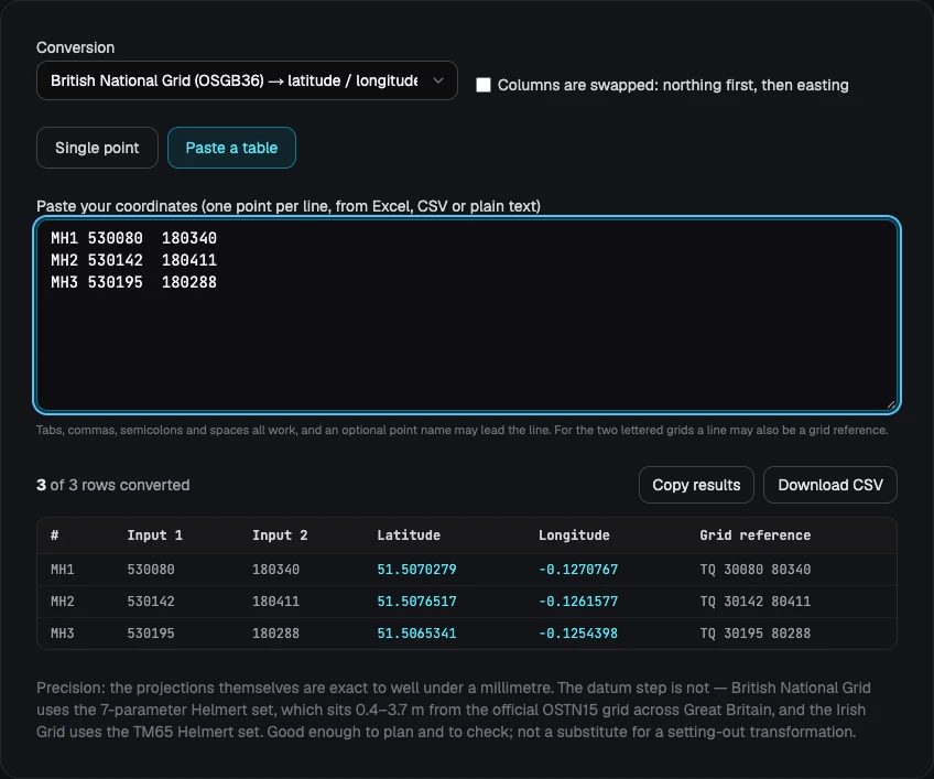
In Altivo, a coordinate table pastes in directly: X, Y or X, Y, Z from Excel, a CSV, or copied straight out of a CAD listing, with the separator auto-detected. Large coordinate values — British National Grid, State Plane feet, UTM, whatever the source — shift toward zero automatically so the drawing and DXF export stay numerically stable in any CAD package, without touching chainage or levels. From there the plan view places the route, gradients and cover depth resolve reach by reach, and the long section exports as a dual-scale DXF with clean layers and editable text — the full workflow is in sewer long section to DXF, step by step. For chainage, elevation and invert level once the points are in, see how to read a utility long section.
Not sure which grid a file is in, or need to check a point before it goes near a drawing? The free easting/northing to latitude and longitude converter covers all five grids in this article — British National Grid, Irish Grid, ITM, UTM and every US State Plane zone — for a single point or a whole pasted table.
Frequently asked questions
What is easting and northing? Easting is the distance east of a grid origin, in metres or feet; northing is the distance north of it. Survey and CAD convention lists easting first, northing second — the same order as X and Y, the opposite of latitude and longitude. That reversal is the most common reason a coordinate looks plausible but plots in the wrong place.
How do I convert easting and northing to latitude and longitude? Identify the grid the numbers came from, then run the pair through that grid's projection and datum step. British National Grid, Irish Grid, ITM, UTM and the 124 US State Plane zones each use different ellipsoids and false origins, so one formula does not cover them all.
What is the difference between OSGB36 and WGS84? OSGB36 is the historic British datum on the Airy 1830 ellipsoid; WGS84 and ETRS89 use the modern GRS80 ellipsoid and satellite positions. The two disagree by roughly 100 metres at the same point, so a coordinate must state which one it is in.
What is the difference between the Irish Grid and ITM? The Irish Grid (TM65) is confined to a single 500,000 by 500,000 metre square on the modified Airy ellipsoid. ITM, introduced in 2001, sits on ETRS89/GRS80 with a false origin of 600,000 mE and 750,000 mN, so its numbers run 400,000–740,000 east and 520,000–970,000 north — the two never overlap in value.
What is a US State Plane coordinate? State Plane is 124 zones covering the 50 states, each a small projection tuned so distortion stays under about 1 part in 10,000. A State Plane number means nothing without its zone name, because neighbouring zones reuse similar magnitudes with different false origins.
Should I use the US survey foot or the international foot? Check the drawing rather than assume. The two feet differ by 2 parts per million — a metre or more at a typical State Plane false easting of a few million feet. NIST and NGS retired the US survey foot at the end of 2022, but older files still use it.
From the right coordinate to a finished drawing
Reading an easting and northing correctly is the difference between a route that lands on the right piece of ground and one that does not, found on site rather than on screen. Confirm the grid, confirm the zone or state, confirm which column is which, and treat any datum step as an approximation unless it is explicitly survey-grade.
Already have a table of eastings, northings and levels? Try Altivo free — paste the coordinates, build the plan and the long section, and export a CAD-ready DXF. 14 days, no card required.
Related articles
What is IFC, and how to export a utility network to BIM (3D model)
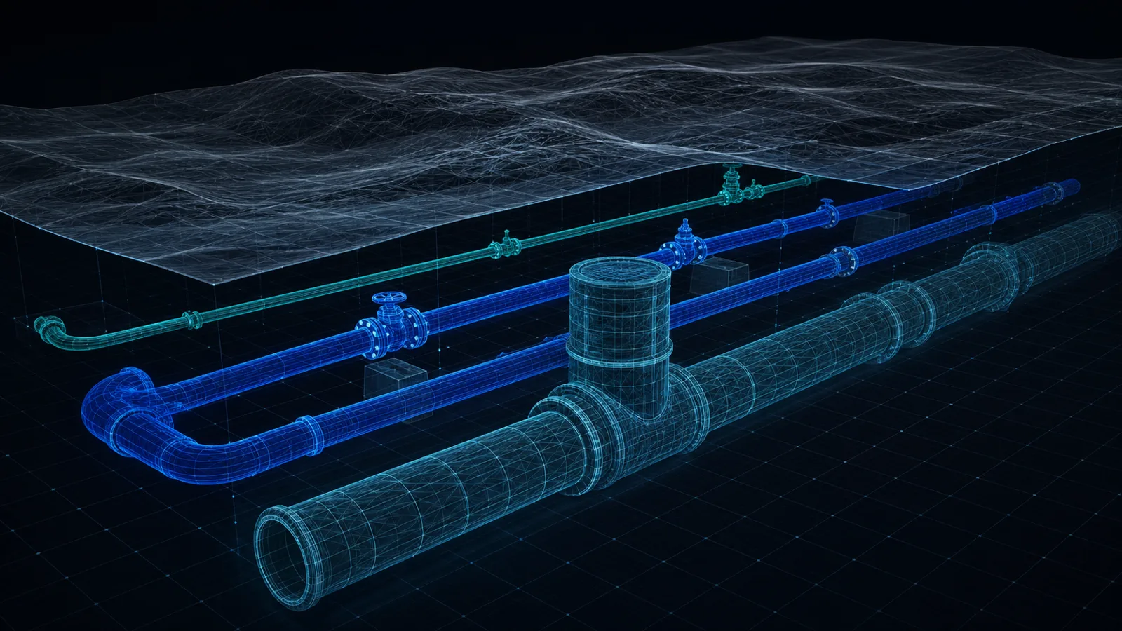
IFC is the open exchange format for BIM models. We explain what it is, why utility designers need it, and how to export your network from Altivo as a georeferenced IFC and 3D DXF.
Base map as an underlay: trace your network route over DXF, PDF or PNG
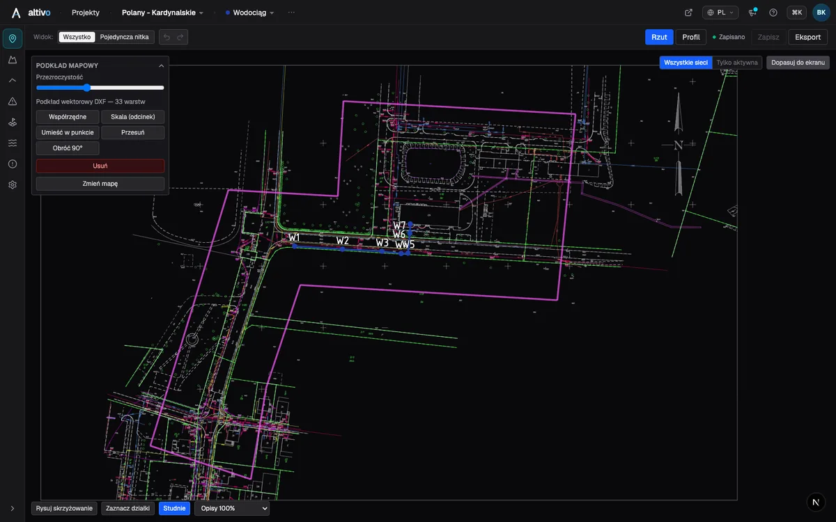
How to load a survey drawing or base map as an underlay on the plan view, calibrate it to real coordinates and trace the network route over it — in the browser, without a CAD seat.
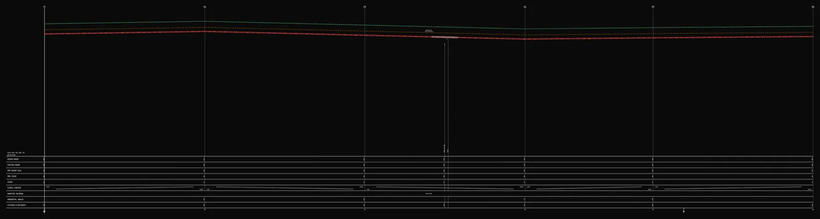
Underground cable long section — power and telecom cable routes
How to draw the longitudinal profile of a buried power or telecom cable route: minimum burial depth by voltage class, crossings, protective ducting, warning tape and a DXF export — in the browser, no CAD.
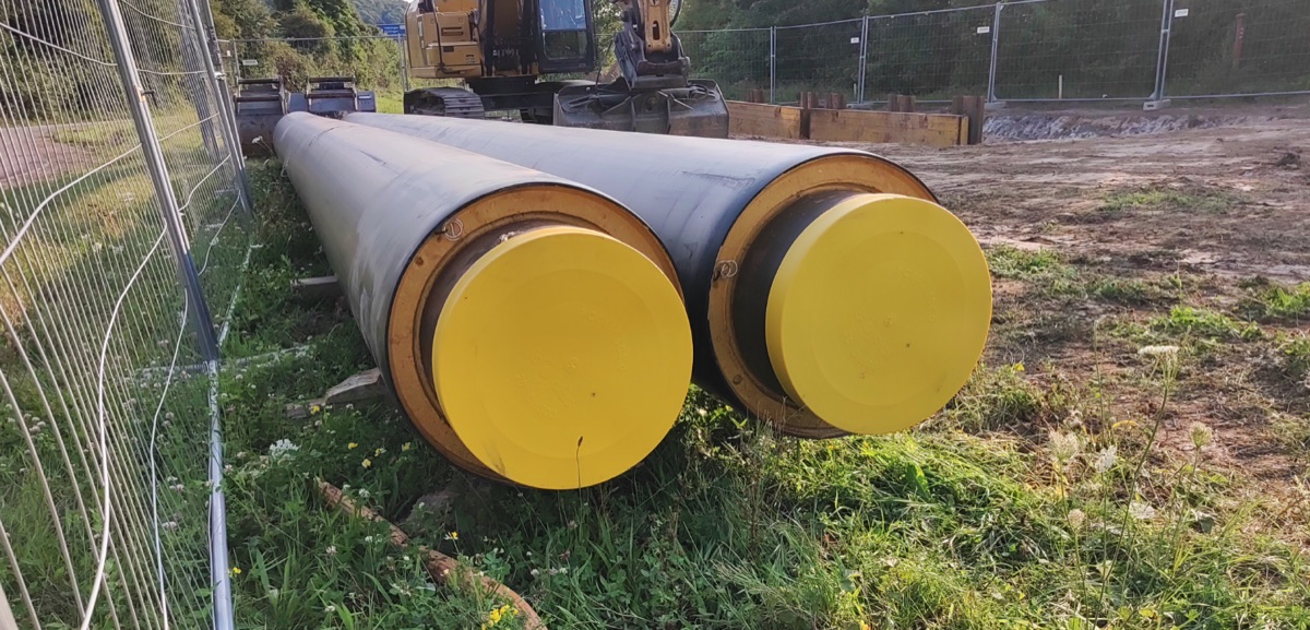
District heating long section — preinsulated pipe in profile
How to draw the longitudinal profile of a district heating network with preinsulated bonded pipe: two diameters (carrier and casing), cover to the casing crown, leak detection, crossings, the profile table and a DXF and IFC export — in the browser, no CAD.
Ready to design without the pain?
Altivo is the fastest way to produce a clean DXF. Try it today.
Start the 14-day trial