
Quick answer
Save the sheet as CSV with the point ID column formatted as text, no thousands separators and every decimal place shown. Map the columns explicitly: easting = E (CAD X), northing = N (CAD Y), elevation = Z. Plain AutoCAD has no numbered survey points, so bring in POINT entities plus text labels, for example as a DXF. Civil 3D imports COGO points through a point file format such as PNEZD or PENZD, which must match the column order exactly.
Note: This article describes a practical workflow for design and as-built data in utility CAD. The survey documentation is the authority on the coordinate system, datum, zone and height datum of your points. Menu paths in AutoCAD and Civil 3D vary between versions and language packs.
The surveyor has sent the points as an Excel sheet: point ID, easting, northing, elevation, perhaps a description. In CAD you want numbered points in the right place at the right height. It sounds like a five-minute job, and in practice it fails on details: Excel turns 0101 into 101, a thousands separator moves a point by orders of magnitude, PNEZD gets mixed up with PENZD, and a foot-based file ends up in a metric drawing.
This guide walks from the spreadsheet to the drawing, with a sample CSV to try: comma-separated, decimal points, numeric IDs with leading zeros, elevations included. The coordinates in it are illustrative projected values in metres.
Step 1: Prepare the spreadsheet
Most import errors are made before CAD is even open. Check five things:
- Point IDs as text. When Excel opens a CSV it reads
0101as a number and shows101. The leading zero is gone, and it stays gone in every CSV you save from that sheet. Load the CSV through Data → From Text/CSV and set the ID column to Text, or format the column as Text before typing the IDs. - No thousands separators. Excel saves a CSV with the values as they are displayed. A cell formatted as
529,812.46is written exactly like that, and Excel wraps that field in quotes in a comma-separated file. Use a number format without thousands separators. - Show every decimal place. For the same reason, a column formatted to zero decimals loses its centimetres in the CSV. The full values usually survive in the XLSX, so re-export from there with enough decimals showing — at least as many as the survey delivers (usually two or three).
- Know your delimiter and decimal separator. With English regional settings, CSV (Comma delimited) uses commas between fields and decimal points; with many continental European settings Excel writes semicolons and decimal commas instead. CSV UTF-8 writes UTF-8; the plain CSV option uses the Windows code page. The tool reads UTF-8 (recommended) or explicitly selected Windows-1252. For other code pages, save a CSV UTF-8 copy first.
- Know your units. Survey data in the UK, Ireland and most of the world is in metres; US State Plane data is often in feet. The CSV to DXF tool works in metres only and does not convert feet. Convert horizontal coordinates and elevations before importing foot-based data, and confirm which foot was used: the US survey foot (1200/3937 m) and the international foot (0.3048 m) differ by about two parts per million, so the positional difference grows with the coordinate values on both axes.
Step 2: Map the columns explicitly — E, N, Z
In CAD the X axis points east and the Y axis north, so easting goes to X and northing to Y:
| Role | Usual column names | CAD | What to check |
|---|---|---|---|
| E | Easting, E | X | Grid and zone from the survey documentation |
| N | Northing, N | Y | Same grid and zone as the easting |
| Z | Elevation, Level, RL | Z | Height datum stated with the survey |
Map columns by their meaning, not by their position or size. Headers called X and Y are ambiguous: in several surveying conventions X is the northing, in CAD it is the easting. Value ranges are not proof either — in the British National Grid, for example, eastings and northings can both be six-digit numbers of similar size, and outside a known grid a large number can be either axis. Rely on the column description, the source coordinate system and at least one known control point. How eastings and northings differ between grids is explained in Easting and Northing: British National Grid, ITM and US State Plane in CAD.
Elevations stay what they are. In this workflow Z values are copied unchanged. The Altivo tool does not convert between height datums (for example from ellipsoidal GNSS heights to Ordnance Datum Newlyn or NAVD 88). If the point list and the design use different height datums, clear that up with the surveyor first. If some rows have no elevation, don't let them quietly become 0.00 m — fill the column or work in 2D on purpose.
Step 3a: Plain AutoCAD — points with labels
AutoCAD itself has no "numbered survey point". A POINT object is only a position; the point ID has to sit next to it as text (or as a block attribute). There are three common ways in:
- Command line: build a helper column in Excel that joins
E,N,Zwith decimal points, copy it, switch AutoCAD to the World Coordinate System (_UCS,_World), start_MULTIPLEand_POINT, and paste the rows into the command line. The leading underscore makes the English command names work in every language version. The comma separates coordinates here, so decimal commas and thousands separators must be removed beforehand. This gives you positions, but no point IDs. - Script file (.scr): put the same lines into a script and run it with
_SCRIPT; extra text commands can place the IDs. It works, but scripts are fragile with spaces and special characters in labels, because a space acts like pressing Enter. - DXF with points and labels: paste the table into our free CSV to DXF tool or choose the file, map the point ID, easting, northing and optional elevation columns, and download a DXF. It contains POINT objects at exactly the absolute coordinates and the point IDs as text, unchanged and with leading zeros. Elevations are written only if you map a Z column, and a connecting line in table order appears only if you switch it on. Comma, tab and semicolon delimiters, decimal points or commas and quoted fields are read; rows with errors are listed and block the entire export until corrected.
The layer names in that DXF are the same in every language version of the tool, so templates and layer filters keep working: points on PUNKTE, labels on PUNKTNUMMERN and the optional line on VERBINDUNG — German for "points", "point numbers" and "connection".
The DXF is drawn in metres and declares metres in its unit header (INSUNITS = 6). Open it directly to preserve its absolute coordinates. If inserting or attaching it to another drawing, use insertion point 0,0,0 and rotation 0, and check the unit scale. Your drawing's units are a separate setting: if the target drawing is set up in millimetres or feet, check the unit scaling when you insert it (for example with _INSERT or as an external reference), or the route ends up a factor of 1000 or about 3.28 out. Scaling on insertion only multiplies coordinates by a unit factor — it does not change the coordinate system and is no substitute for checking which foot and which grid the target drawing uses. For visible point markers, adjust PDMODE/PDSIZE in the target drawing if needed.
Step 3b: Civil 3D — COGO points through a point file format
Civil 3D works with COGO points, which carry a point number, an optional name, northing, easting, elevation and description, plus label styles and point groups. You import them with _IMPORTPOINTS (Import Points). The key choice is the point file format, because it defines the column order:
- PNEZD = Point, Northing, Easting, Z, Description — point number, northing, easting, elevation, description.
- PENZD = Point, Easting, Northing, Z, Description — point number, easting, northing, elevation, description.
Look at the file before you pick one. A list in the order ID, easting, northing, elevation — like the sample above — is PENZD, not PNEZD; choosing the wrong one swaps easting and northing. More things to watch:
- The supplied formats come as "comma delimited" and "space delimited" variants. A file with semicolons and decimal commas matches neither — re-save it with decimal points and commas, or create your own point file format.
- The point number is an integer. An ID such as
0101becomes point number 101, andMH-12cannot be a point number at all. Civil 3D points also have a name, which accepts text: a custom point file format can read the ID column into the point name, or you can keep the ID in the description. Which one fits depends on your label styles and on what happens to the points downstream. - If point numbers clash with existing points, Civil 3D offers to renumber, overwrite or merge. Renumbering breaks the link to the survey list, so decide deliberately.
- The Import Points dialog has optional advanced settings for elevation adjustment, coordinate transformation and coordinate data expansion. Z values and coordinates pass through unchanged only while these are off. Turn them on only if the drawing has a properly set-up coordinate system and you want exactly that adjustment.
If all you need is a set of numbered points as a base, the DXF from step 3a works in Civil 3D too; for surfaces, point groups and label styles, COGO points are the right tool.
Step 4: Convert first, then import
The coordinate system, datum and zone of your points must be confirmed from the survey documentation, not guessed from the numbers. Neither the CSV to DXF tool nor a plain import converts anything. If the points come as latitude and longitude, convert them to the drawing's grid first — the easting/northing converter handles the British National Grid, ITM, Irish Grid, UTM and US State Plane. Where a datum shift is needed, the converter uses published Helmert parameters rather than a local grid correction. Treat the result as approximate; it is not meant for setting out, boundaries or tying into a control network. For survey work, use the transformation specified by the surveyor or mapping authority, such as OSTN15 for British National Grid. Latitude and longitude pasted into a metric drawing as they are produce values around 50 and −1, not a usable location.
From points to a long section
If the points run along a route — manholes on a sewer run in flow order, say — you can turn them straight into a long section. From the CSV to DXF tool, up to 200 points go into the long-section preview from Excel without signing up, after you confirm that the table order defines the route and that any Z values, if present, are ground elevations. The point IDs become the point names, the coordinates stay exactly as entered, existing elevations become the ground elevations and the chainage follows from the horizontal distances between consecutive points. The coordinates never leave your browser tab. How chainage, ground and invert levels then fit together is explained in How to read a utility long section.
Checklist before you import
- Coordinate system, datum and zone confirmed from the survey documentation? No mix within one file?
- Columns mapped using the survey documentation and a known control point (value ranges alone are not conclusive)?
- Point IDs stored as text, leading zeros still there?
- No thousands separators, full decimals?
- Units in metres for the CSV to DXF tool — horizontal coordinates and elevations converted if the survey is in feet?
- Decimal separator suits the target: points for the AutoCAD command line and the supplied Civil 3D formats?
- Civil 3D: PENZD for "easting first", PNEZD for "northing first"; text IDs in the name or description; optional adjustments off for a pass-through import?
- Same height datum in the point list and the design?
- Metric DXF scaled correctly into a millimetre or foot drawing?
Frequently asked questions
What does PNEZD mean in Civil 3D? PNEZD stands for Point, Northing, Easting, Z, Description: point number first, then northing, then easting, then elevation and description. PENZD is the same with easting before northing. Many spreadsheet exports list easting first, so check the file before choosing a format — applying PNEZD to an easting-first file swaps the axes.
Why do my point IDs lose their leading zeros? Usually Excel has already removed them when it opened the CSV, because it reads 0101 as the number 101. Import the CSV through Data → From Text/CSV and set the ID column to Text. In Civil 3D the point number itself is an integer, so keep text IDs such as 0101 or MH-12 in the point name (via a custom point file format) or in the description.
Are elevations converted during the import? Not in the workflow described here. The Altivo tool passes Z values through unchanged and converts neither units nor vertical datums. Civil 3D also keeps them unchanged only when the optional elevation adjustment and coordinate transformation are turned off.
My survey is in feet. Can I use the CSV to DXF tool? Only after converting it. The tool works in metres only and does not convert feet. Convert horizontal coordinates and elevations to metres first, and confirm whether the data uses US survey feet or international feet.
Why do my points land in the wrong place in AutoCAD? The usual causes are swapped easting and northing, decimal commas in the command line, thousands separators from Excel, a different coordinate system or zone than the drawing, latitude and longitude instead of grid coordinates, or the wrong units when inserting a metric DXF.
Sources
- Autodesk Civil 3D Help: About Point File Formats
- Autodesk Civil 3D Help: To Import Point Data — point names, point identity settings and the optional elevation adjustment, coordinate transformation and coordinate data expansion
Try the tool
Turn a point list from Excel or CSV into DXF — point IDs kept as text, optional elevations, absolute coordinates in metres unchanged.
Open the CSV to DXF tool →Related articles
Civil 3D alternative for pipe long sections (plan & profile)
When Civil 3D is right for a utility long section and when it is overkill: an honest comparison, where a focused tool stops, and Excel table to DXF.
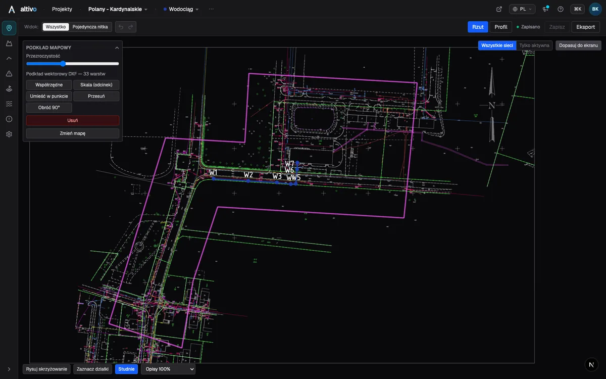
Base map as an underlay: trace your network route over DXF, PDF or PNG
How to load a survey drawing or base map as an underlay on the plan view, calibrate it to real coordinates and trace the network route over it — in the browser, without a CAD seat.
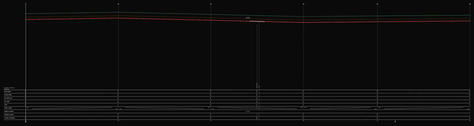
Underground cable long section — power and telecom cable routes
How to draw the longitudinal profile of a buried power or telecom cable route: minimum burial depth by voltage class, crossings, protective ducting, warning tape and a DXF export — in the browser, no CAD.
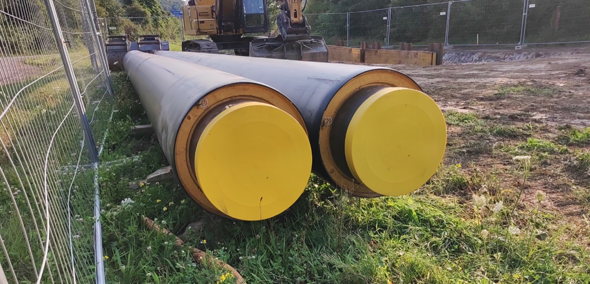
District heating long section — preinsulated pipe in profile
How to draw the longitudinal profile of a district heating network with preinsulated bonded pipe: two diameters (carrier and casing), cover to the casing crown, leak detection, crossings, the profile table and a DXF and IFC export — in the browser, no CAD.
Ready to design without the pain?
Altivo is the fastest way to produce a clean DXF. Try it today.
Start the 14-day trial